CCNA Prep: Misinformation in Boson NetSim Labs
Many people speak very highly of Boson and their ExSim and NetSim products. From my experience so far, NetSim definitely has some advantages over Packet Tracer for cert prep, and the labs are (mostly) pretty solid, and they ask good questions in most of their labs (some of them are real stinkers though). The problems are in the details of the answers and explanations they provide.
In an effort to help, I've started compiling a list of errors I've encountered and corrections to those errors. This isn't an exhaustive list because I've only given myself 3 weeks to get through these labs, but I'm trying to track what I can, especially the more egregious errors.
This is partly so that I can reinforce the correct information for myself, but I hope it's useful to someone else out there too.
August 14 2024 Update: I eventually gave up on this because of how time consuming it was to keep checking for accuracy (yes, there are that many errors). My suggestion to anyone using NetSim is to not pollute your brain with the half-baked explanation sections.
Lab: Explore Spanning Tree Protocol Port Roles
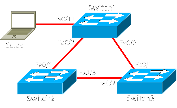
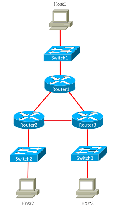
Lab Topology
Task 2: Determine STP Port Roles
Lab Question and Incorrect Answer
Question: Why is the FastEthernet 0/3 interface on Switch2 blocked instead of the FastEthernet 0/2 interface on Switch3?
Answer: The FastEthernet 0/3 interface on Switch2 is blocked because its port number is higher than the port number of the FastEthernet 0/2 interface on Switch3.
Correct Answer and Explanation
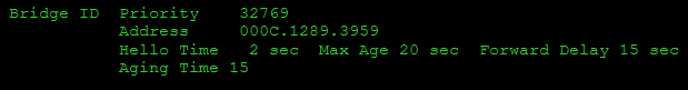
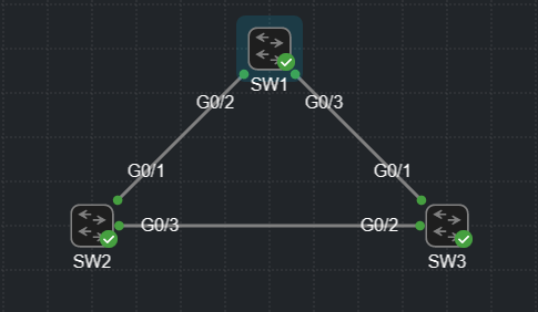
As you can see from the topology, Switch2 and Switch3 should both have an equal cost to get back to the root bridge (Switch1). So who wins the designated port role in the link between them? To answer that, we need to compare their Bridge IDs (see below screenshots).
| Switch1 |
 |
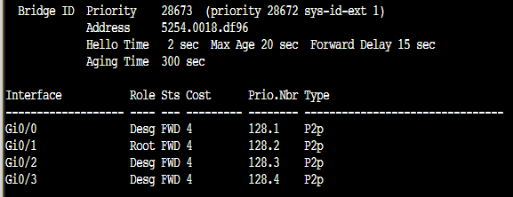
| Switch2 |
|
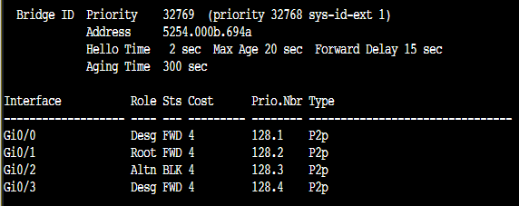
| Switch3 |
|
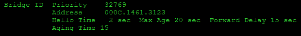
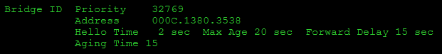
Remember that the bridge ID is a concatenation of the bridge priority and the base MAC address. Because the priorities are all equal, we need to compare the MAC address for each switch (lowest value wins). Switch1 has the lowest MAC address, so that's why it won the root bridge election. Switch3 has the second lowest MAC address, so it wins the link between it and Switch2. The port numbers and port priorities don't come into play unless there are multiple links between network nodes.
I'm not sure how the Boson simulator gets the base MAC address. Usually you can see it in the show version command, but there's nothing there.
We can prove that the bridge ID is the deciding factor by dropping Switch2's priority down a notch (-4096). To ensure Switch1 remains root, I'll drop its priority down two notches (2x -4096). Unfortunately, I wasn't able to get NetSim to behave in the expected way, but both Packet Tracer and Cisco Modeling Labs (CML) agree with reality.
Here's the same NetSim lab topology in CML.
Before manually adjusting the bridge priorities, Switch3 had won the designated port for the link between it and Switch2. However, as you can see from the image below, Switch2 took over the designated port after the adjustments were made.
| Switch1 |
|
| Switch2 |
|
| Switch3 |
|

Lab: Implement CDP and LLDP
Lab Topology
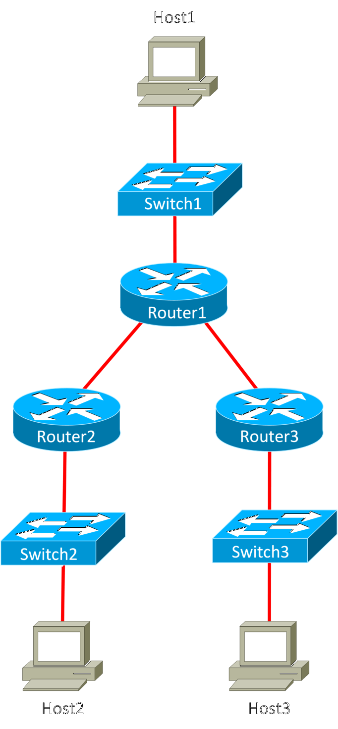
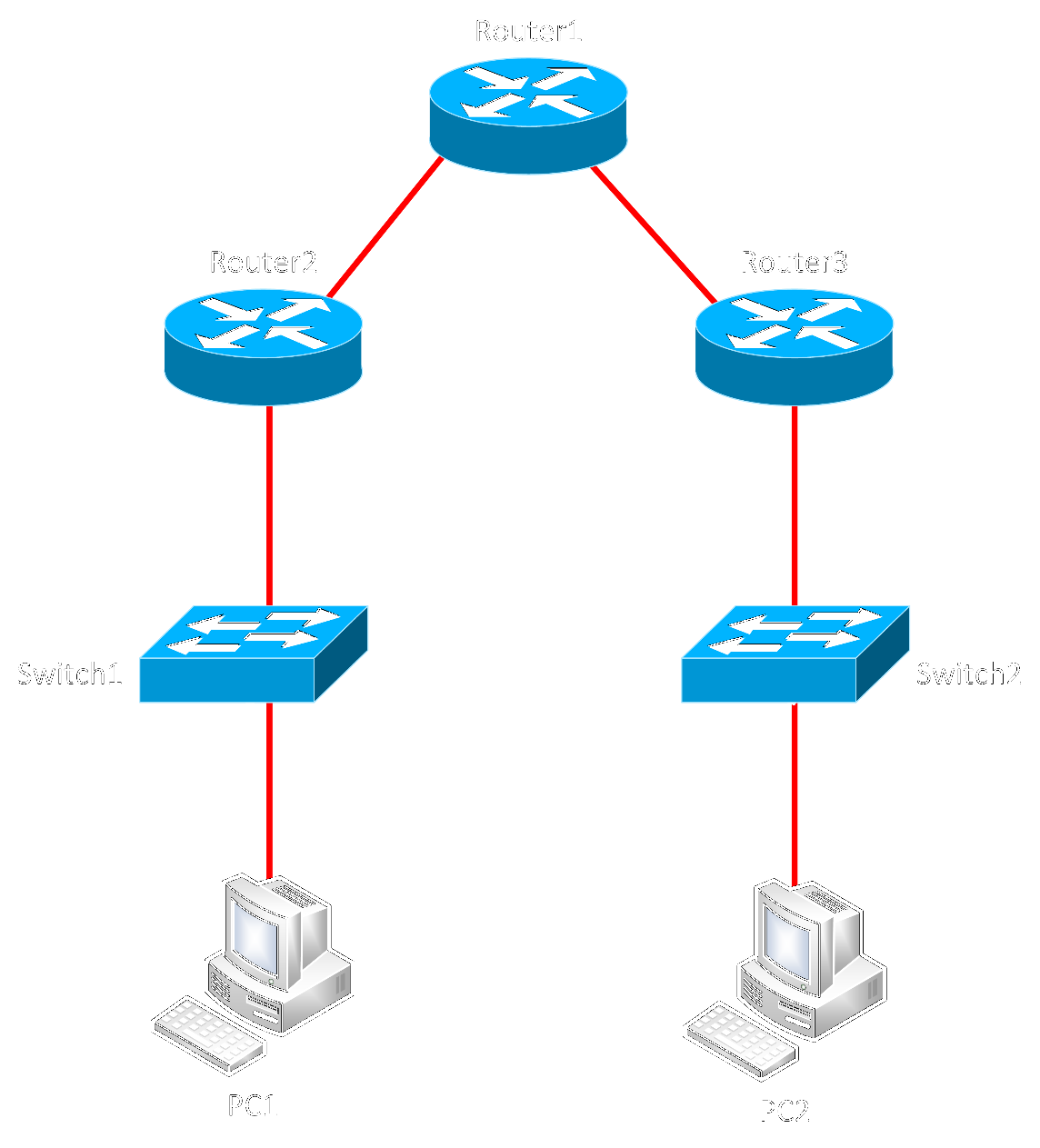
This isn't misinformation, but it really threw me off for a minute. There is a missing link in the topology diagram between Router2 and Router3. The image on the left is what Boson gives you. The image on the right has the missing link filled in.
Lab: Implement Rapid-PVST+
Honestly, this entire lab reads like somebody replaced every instance of the word "PVST" with "Rapid-PVST." You should probably skip it so that it doesn't pollute your brain.
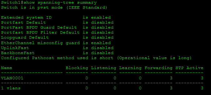
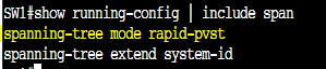
It's actually not readily apparent whether or not the simulator can even use rapid spanning tree based on the output from show spanning-tree summary and show running-config | include span. Even after explicitly configuring rapid-pvst in global config mode, both commands suggest the switch is running pvst and not rapid-pvst.
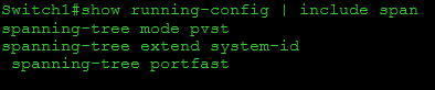
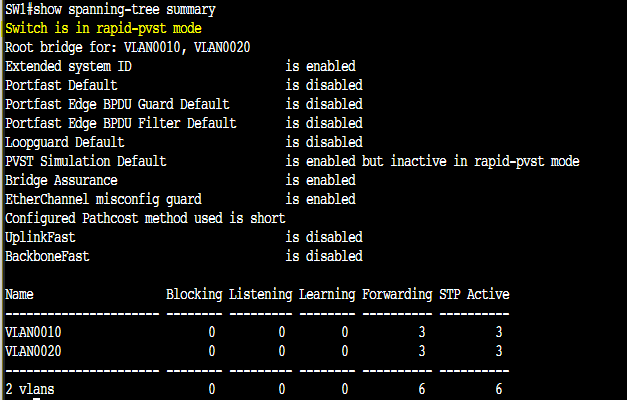
Here's the same output from Cisco Modeling Labs (CML) where it is easy to confirm that the switch is using RSTP.
With all of that said, since STP and RSTP and very similar, there isn't a lot of information in the lab that is blatantly false (though they keep telling you to wait for the network to converge which they expect to take much longer than RSTP really would). The only particularly horrible error they make is detailed in task 2 (see below). Actually, if you do this lab, just skip task 2 because it's trash.
Lab Topology
Task 2: Explore Rapid-PVST+ Port States and Configure PortFast
Lab Question and Incorrect Answer
Question: What are two other states in which a Rapid-PVST+ port can transition? What are the functions of those states?
Answer: There are two other states that Rapid-PVST+ ports can transition through during network convergence: listening and learning. The listening state is typically displayed in the output of the show spanning-tree command as LIS. In the listening state, a port becomes able to send and receive BPDUs, which carry STP information. However, a port in the listening state discards data frames and does not populate the MAC address table.
The learning state, on the other hand, is typically displayed as LRN. After a port transitions to the learning state, it begins to populate the MAC address table. In addition, a port in the learning state will continue to send and receive BPDUs. However, a port in the learning state will continue to discard data frames.
Correct Answer and Explanation
The four states that Boson describes here are STP port states, not RSTP states. RSTP only has 3 port states: discarding, learning, and forwarding. Below is a table from Cisco comparing STP and RSTP port states. You can see the full document from Cisco here.
| STP (802.1D) Port State | RSTP (802.1w) Port State | Is Port Included in Active Topology? | Is Port Learning MAC Addresses? |
|---|---|---|---|
| Disabled | Discarding | No | No |
| Blocking | Discarding | No | No |
| Listening | Discarding | Yes | No |
| Learning | Learning | Yes | Yes |
| Forwarding | Forwarding | Yes | Yes |
Lab: Boson CCNA Challenge Lab 2
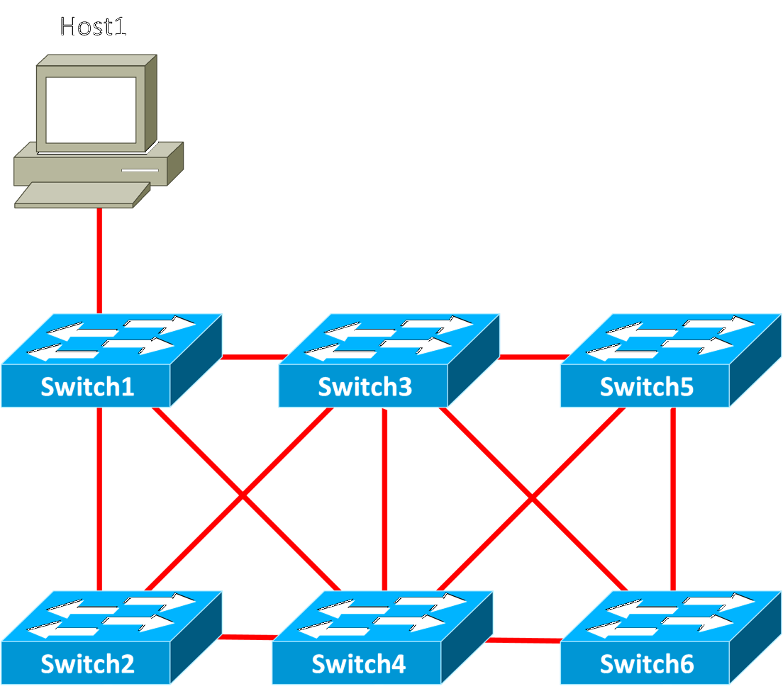
Lab Topology
Task 2: Configure the Advanced Layer 2 Network
Lab Question and Incorrect Answer
Question: On Switch2, issue the commands to configure the range of ports that connect to Switch1 as EtherChannel group 1. Ensure that the resulting EtherChannel port is placed into an LACP state that responds to LACP packets it receives but does not initiate negotiation.
Answer: Based on the output, you can determine that the EtherChannel link is working. For Port-Channel 1 and its line protocol to transition to the up state, every physical interface in the port channel interfaces must be configured the same way. In addition, the two logical interfaces must be configured with the same number of physical ports and to use the same aggregation protocol, if any is configured.
Correct Answer and Explanation
I waffled a bit on whether or not this was worth including because it's not a horrible error, but it does put some constraints on the formation of LACP LAG interfaces. Not all ports really need to be in the same configuration in order for the LAG interface to go up. They also don't need the same number of ports on either side. Granted, it is obviously best if these two things are true, but the interface will go up anyway if there are ports that it can use.
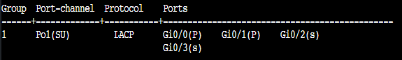
What will really happen is the nonconforming or extra ports will be placed in a suspended state. As an example, I created two switches, LAGSW1 and LAGSW2, and configured LAGSW1 with a 4port LAG and LAGSW2 with a 2-port LAG.
LAGSW1 output for show etherchannel summary
and output for show interfaces status for LAGSW1

LAGSW2 output for show etherchannel summary
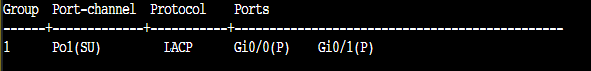
Again, the LAG link is up between the two switches. LAGSW1 just has a couple extra ports that it suspends because they aren't being used. This is part of how LACP operates and why it is useful. It negotiates around these sorts of shortfalls.
Lab: Explore OSPFv2 DR and BDR Router Selection
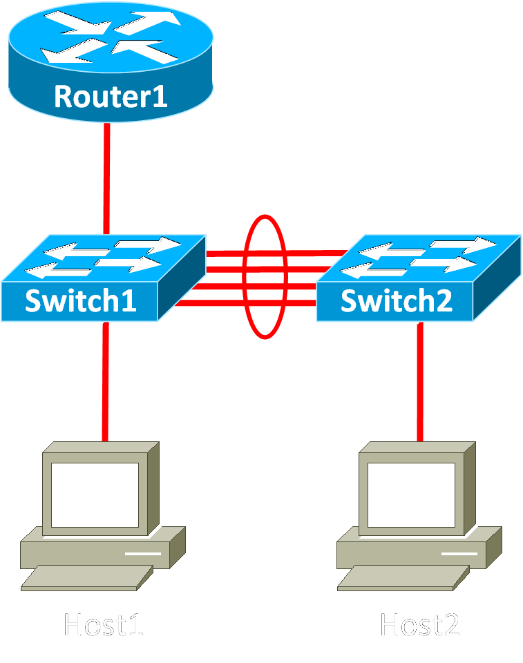
Lab Topology
Task 2: Explore DR and BDR Selection
Lab Question and Incorrect Answer
Question: On Router2, repeatedly display OSPF neighbor information to watch the election process. What state is the adjacency between Router1 and Router2 in after the network converges?
Answer: Based on the output, you can determine that Router1 is neither the DR nor the BDR for the link between Router2 and Router1. This is because Router1 has an OSPF priority of 0 and is no longer participating in DR and BDR selection. Router1’s state in the relationship is now nothing because it is not participating in the election at all. It is important to note that when a router is neither the DR nor the BDR but is still allowed to participate in the election, the OSPF neighbor state will be reported as DROTHER.
Correct Answer and Explanation
This question is posed after you manually configure Router1's f0/0 interface with an OSPF priority of 0. This makes the interface ineligible for DR/BDR elections; Boson gets that part right. However, they go off in some crazy tangent direction and start making things up after that.
A router interface on an OSPF broadcast network will always be DR, BDR, or DROTHER. The only reason a relationship would show as a "-" is if the network type for that link did not hold DR/BDR elections at all (example: on a point-to-point network).
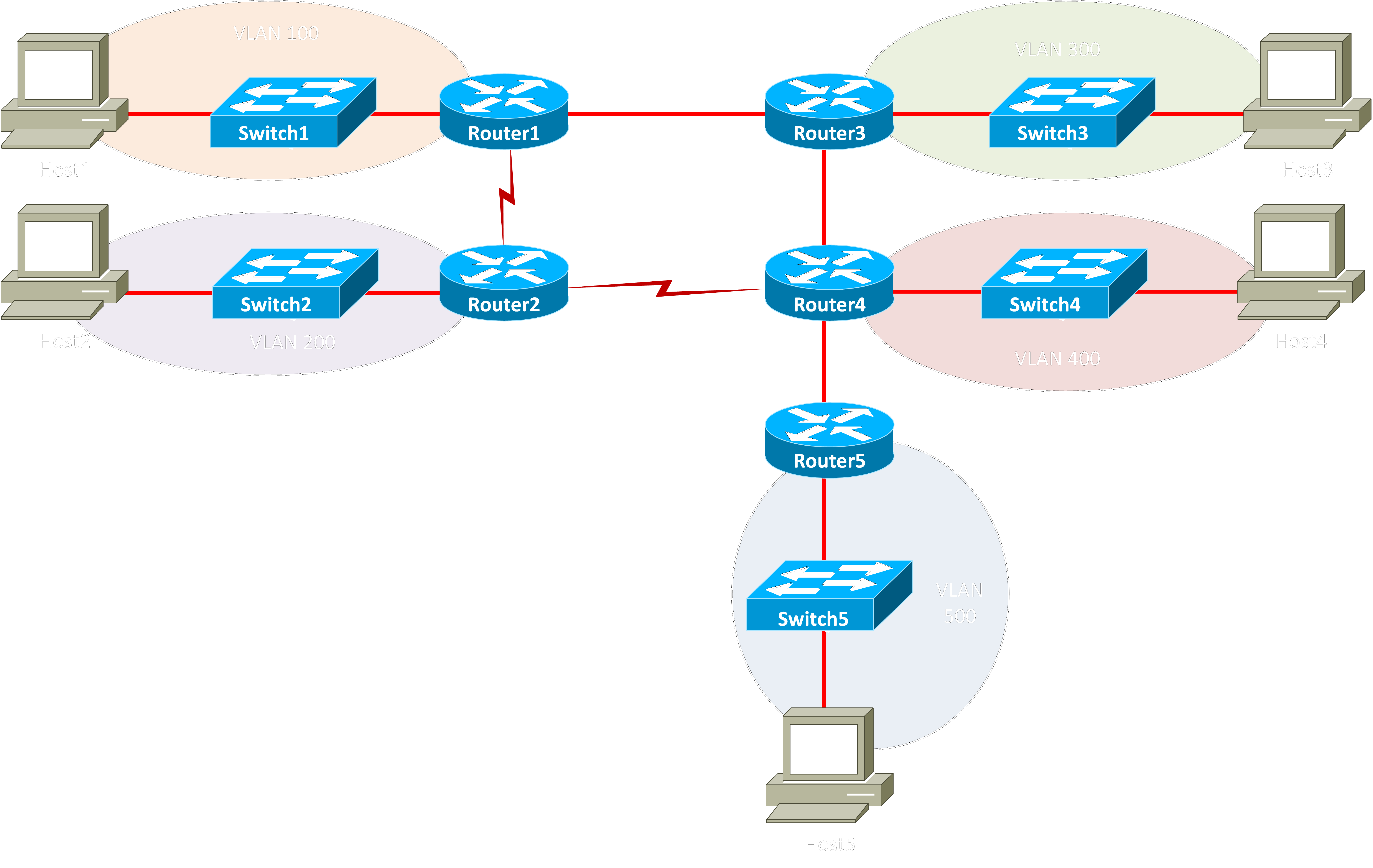
Let's check what happens in CML. Below is an image of the topology I used.
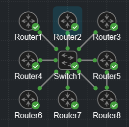
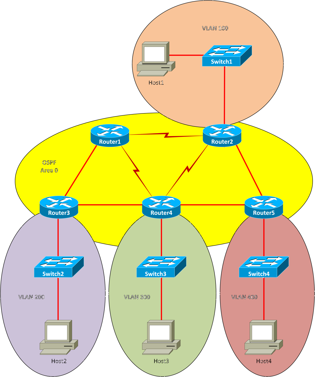
All routers are configured to participate in OSPF area 0 on their G0/0 interfaces which are all connected to each other via Switch1. All routers are also configured with a loopback interface which has an IP address of x.x.x.x where x is the number in the router's name (1.1.1.1 for Router1, 2.2.2.2 for Router2, etc). As expected, Router8 has been elected the DR and Router7 has been elected the BDR.
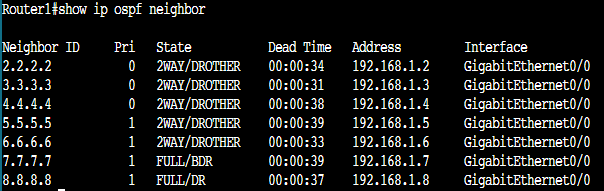
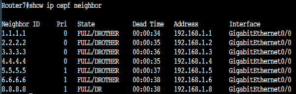
After joining every router to the OSPF area and confirming expected relationships, I changed the OSPF priority to 0 on the G0/0 interfaces for routers 1-4. Routers 5-8 kept the default priority of 1. Out of extreme caution, I cleared the OSPF process on routers 1-4 with clear ip ospf process and waited for the network to converge. Below is the output for show ip ospf neighbor on Router1. As you can see, all routers with priorities set to 0 are still displaying DROTHER, not "-".
And here's the same output from Router7 (the current BDR).
Furthermore, we can even see that Boson's NetSim doesn't even seem to agree with its own buggy behavior. If we check Router2's side of the link with show ip ospf neighbor(as they do in the lab), we see that the relationship with Router1 is Full/ -, but if we check the link from Router1 with show ip ospf interface brief, we see that the interface is actually reporting its own relationship as DROTHER.
Here's the link from Router2

and from Router1

Even after all of this, I still went hunting for some justification for why Boson has this explanation in the lab. Cisco makes no mention of the behavior they describe and I couldn't find anything anywhere that even hinted at this behavior. I even found multiple people in Cisco's community support saying that you should always expect to see DR, BDR, or DROTHER for any network that holds DR/BDR elections.
Lab: Implement Route Selection
Lab Topology
Task 1: Influence Route Selection by Using AD
Lab Question and Incorrect Answer
Question: Issue the necessary commands to display the routing table. What paths to the 203.0.113.0/30 network exist in the routing table now. Why?
Answer: Based on the output, you can determine that Router4 has replaced the static route to the 203.0.113.0/30 network through Router3 with three of the original four OSPF paths to the network. This is because the static route to 203.0.113.0/30 through Router3 is now configured with an AD of 111, which is less trustworthy than OSPF’s default AD of 110. The path to 203.0.113.0/30 through Router3 is no longer inserted into the routing table.
Correct Answer and Explanation
Boson starts this lab by having you check the routing table for OSPF routes. They then have you set a static route with an administrative distance (AD) of 111 which is 1 value above the default AD for OSPF routes. This has the effect of creating a floating static route which is a sort of fail-safe mechanism.
Boson seems to think that the floating static route will somehow eat the same route learned via OSPF. This is incorrect because-well... because that's not how that works. What is particularly interesting is that Boson makes this claim while providing a screenshot that directly contradicts the point they are trying to make.
Below is the screenshot from the first time they ask you to check the routing table
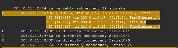
and here's the screenshot from after you create the floating static route.
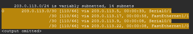
Can you spot the difference? No? That's because there isn't one. The routes to 203.0.113.0/30 are exactly the same before and after you create the static route. For the sake of completeness, let's look at a similar scenario in Cisco Modeling Labs. Below is my lab topology (ignore the switch in the middle).
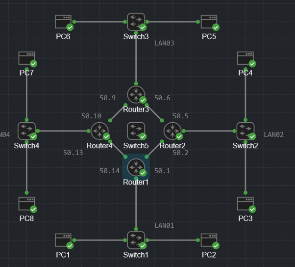
The routers in the middle are all configured to learn routes using OSPF. The topology is set up in a way that gives Router1 two equal-cost routes to LAN03 (192.168.30.0/24). I created a route using ip route 192.168.30.0 255.255.255.0 192.168.50.13 111 then checked the routing table.
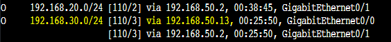
Look at that! We see the same expected behavior; the same route can simultaneously exist as a floating static route AND a dynamically learned route.
Lab: Implement Single-Area OSPFv2
This lab doesn't start out well. The objective section states "Before routers in an OSPF area can exchange information, they must establish a neighbor relationship, which is also known as an adjacency." This is incorrect. OSPF neighbors and OSPF adjacencies are not the same thing. Routers can be neighbors with each other without forming an adjacency. Think of an adjacency as a higher level of OSPF neighbor relationship. On point-to-point links, each neighbor forms an adjacency, but on other types of networks like broadcast networks, routers only form adjacencies with designated routers (DRs) and backup designated routers (BDRs).
This misconception that neighbor = adjacency follows the entire lab. Just know that this is incorrect.
Lab Topology
Task 1: Configure OSPFv2 Router Processes
Lab Question and Incorrect Answer
Question: On Router2, Router3, Router4, and Router5, configure an OSPF process. On each router, use a process ID that matches the virtual local area network (VLAN) ID of the private network to which the router directly connects. What benefit is there to configuring an OSPF process ID in this way?
Answer: One benefit of using the VLAN ID as the OSPF process ID is that it enables the administrator to more easily remember which network is being configured on the router.
Correct Answer and Explanation
Okay, so strictly speaking, this isn't exactly wrong, it's just kind of silly. Routers are layer 3 devices that don't really need to care about VLANs. Sure, some routers may only be connected to one VLAN'd subnet, but what about routers with subinterfaces that attach to multiple VLAN'd subnets? Additionally, what about routers that don't connect to a VLAN'd subnet at all? What process ID do we give them? The final nail in this coffin is that the lab only loosely associates the VLAN IDs with the IP addressing scheme, so all they've done is ADD administrative overhead.
I'm sure there are plenty of reasons to come up with a specific OSPF process ID numbering scheme, but this ain't it.
Task 2: Configure OSPFv2 Router Adjacencies
Lab Question and Incorrect Answer
Question: On Router2, issue the commands to display information about OSPF neighbor relationships that exist on the router. With which routers has Router2 formed relationships? In what state is the relationship?
Answer: The router relationships will thus proceed through the following states after an adjacency is established:
- ExStart
- Loading
- Full or two-way
Correct Answer and Explanation
Routers that end in the 2-way state do not go through the exstart and loading states. Omitting the down and attempt states, the correct order in which routers proceed through OSPF neighbor states is:
- Init
- 2-Way
- Exstart
- Exchange
- Loading
- Full
When routers have reached the full state, they have actually formed an adjacency. You can read more about this process here or you can check the attachments on this page.
Lab: Boson CCNA Challenge Lab 3
This lab is trash. Skip it. Boson keeps making things up.
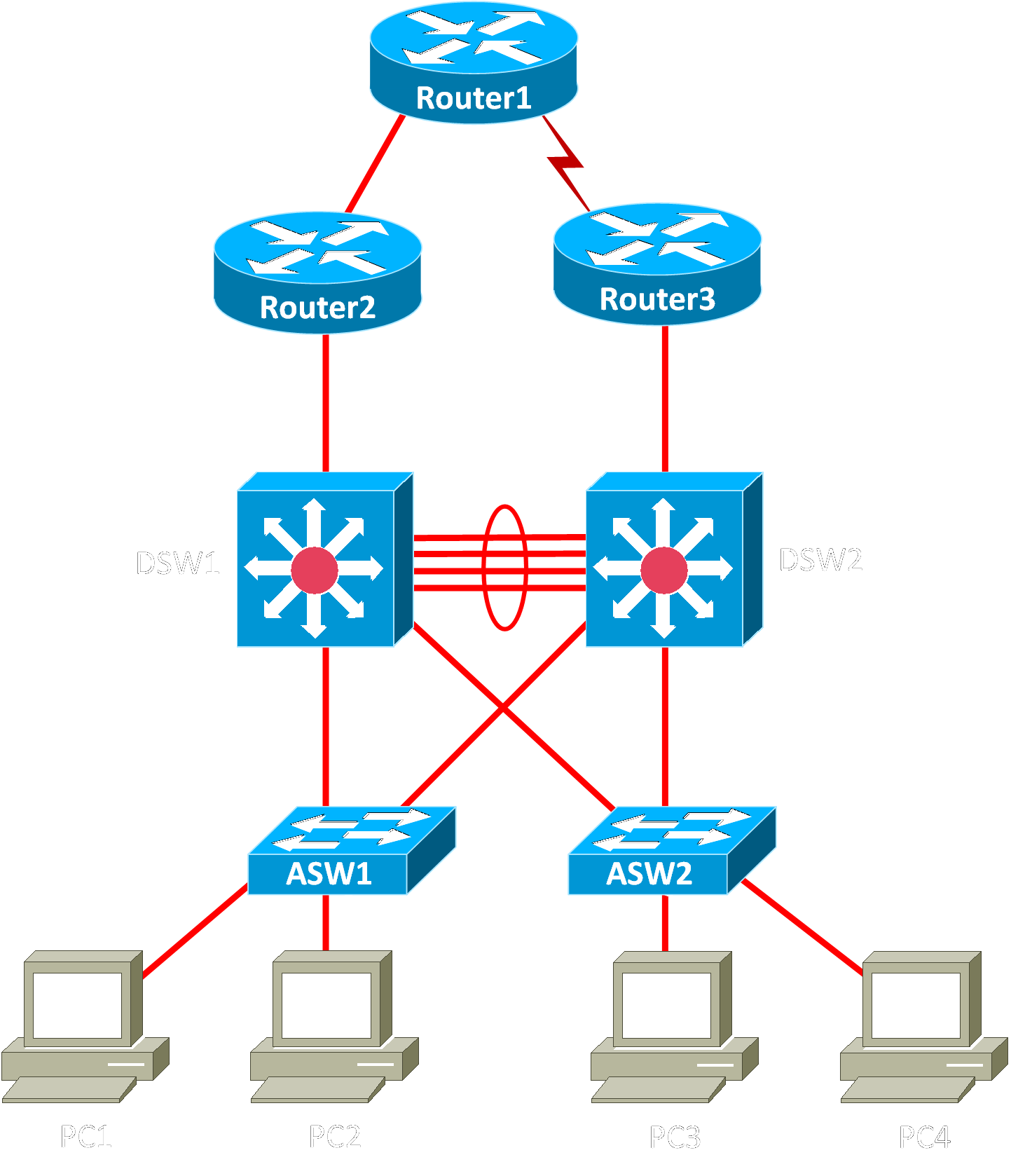
Lab Topology
Task 2: Configuring Default Routes and Static Routes
Lab Question and Incorrect Answer
Question: From ASW1, ping DSW1’s VLAN 100 interface (192.168.100.1) and DSW2’s VLAN 100 interface (192.168.100.2). The pings should fail.
Answer: The pings fail even though ASW1 is configured with an interface that resides on the same VLAN as the VLAN 100 interfaces on DSW1 and DSW2. This is because Layer 2 switches must be configured with a default gateway in order to correctly send and reply to ICMP packets.
Correct Answer and Explanation
This actually directly contradicts a previous lab where you configure an SVI on a switch then ping outside the LAN. The pings succeed even though the switch has no default gateway. They give kind of a trash explanation for it, but, long story short, it's because of proxy ARP.
So what do I think is going on here? Well, at least some (maybe all, I don't really know) layer 2 switches only allow a single SVI to be up at a time. If we run show ip int brief on ASW1, we can see that there are VLAN 1, VLAN 100, and VLAN 200 SVIs configured.
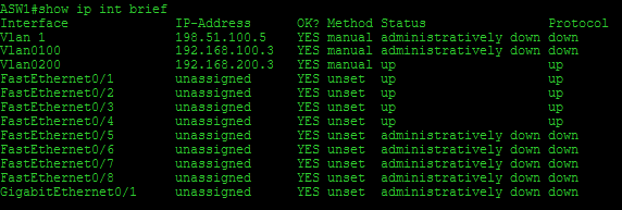
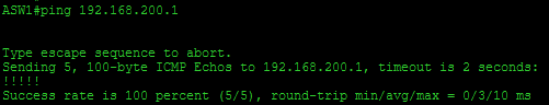
You can see that the VLAN 200 SVI is up and the other two are down. So can we ping on VLAN 200? Why, yes. Yes, we can.
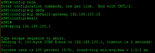
With that said, it is certainly a bit confusing that we can ping 192.168.100.1 after configuring a default gateway. I don't really have a satisfying explanation for that right this second. Just for the sake of completeness, here are the pings going through after adding the default gateway.
I tried doing a traceroute to see what the path actually was from ASW1, but that completely fails out. So, I guess the next best thing is to see what things look like from DSW1. To do that, I enabled ICMP debug output with debug ip icmp then pinged 192.168.100.1 from ASW1 again. Here's the output from DSW1.
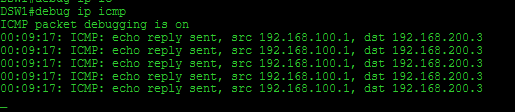
We can see that from DSW1's perspective, it is actually communicating with 192.168.200.3, ASW1's VLAN 200 interface, not ASW1's VLAN 100 interface. So, that's interesting. Let's see what happens if we disable the VLAN 200 SVI on ASW1. Spoiler alert: the pings fail.
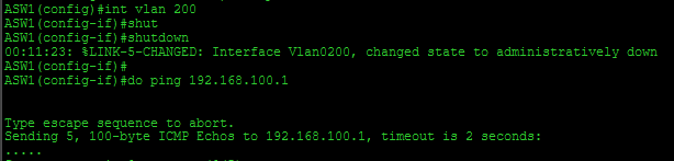
If we turn ASW1's VLAN 200 SVI back on but disable the VLAN 200 SVI on DSW1 and DSW2 (the layer 3 switches are in an HSRP group in this lab, so they both need to go down), we see the pings from ASW1 fail. Furthermore, we don't even see any debug output on DSW1.
I can't replicate this in Cisco Modeling Labs because there isn't a way to add a layer 2 only switch as far as I have been able to tell. I also don't have a physical lab set up right now and-well... this really isn't worth the hassle. In any case, here's my mostly satisfying explanation for what is going on here:
- ASW1 doesn't have a layer 3 interface for which to handle ICMP traffic on VLAN 100 because its VLAN 100 SVI is shut down
- Because ASW1 does have an operational VLAN 200 SVI, it can ping stuff on VLAN 200
- After you configure a default gateway on ASW1, the VLAN 200 SVI has a remote target for which it can send out ARP requests. So it ARPs out for 192.168.100.1 on VLAN 200
- DSW1 hears the ARP requests on VLAN 200 and says "Hey, I know that guy. That's me," and replies to ASW1 because it has proxy ARP enabled
- ASW1 notes that it can reach 192.168.100.1 via its VLAN 200 SVI and sends that traffic to DSW1's VLAN 200 SVI
I don't see anything in ASW1's ARP table to confirm all that, but that could be a bug in the simulator for all I know. Again, it's a mostly satisfying answer, so I'ma run with it and move on.
No comments to display
No comments to display